|
|
汽车零部件采购、销售通信录 填写你的培训需求,我们帮你找 招募汽车专业培训老师
请高人帮忙翻译下
Active Control of Seat Vibrations of a Vehicle Model Using Vario
Suspension Alternatives
Abstract
The dynamic behavior of a non-linear 8 degrees of freedom vehicle model having active suspensions and a PID controlled passenger seat is examined. The non-linearity occurs due to dry friction on the dampers.The suspensions are considered as McPherson strut-type independent suspensions. Three cases of control strategies are taken into account. In the rst case, only the passenger seat is controlled. In the second case,only the vehicle body is controlled. In the third case, both the vehicle body and the passenger seat are controlled at the same time. Since the PID control method can be applied easily and is well known, it has an important place in control applications. The time responses of the non-linear vehicle model due to road disturbance and the frequency responses of the harmonically linearised non-linear vehicle model are obtained for each control strategy. At the end, the performances of these strategies are compared and discussed.
Key words: PID control, Vehicle model, Active suspensions.
Introduction
Vehicle suspension can be treated as a dynamic system using vehicle properties and simulating the response of the vehicle to various inputs and disturbances. Suspension serves the basic function of isolating passengers and the chassis from the roughness of the road to provide a more comfortable ride. Due to developments in the control technology, electronically controlled suspensions have gained more interest. These suspensions have active components controlled by a microprocessor. By using this arrangement, signicant achievements in vehicle response can be carried out. Selection of the control method is also important during the design process. In this study PID controllers parallel to McPherson struttype independent suspensions are used. The major advantages of this control method are its relative simplicity in design and the availability of well-known standard hardware. To simplify models, a number of researchers assumed vehicle models to belinear. However, such models contain non-linearities thatshouldbe takenintoaccount. By includingnon-linearities such as dry friction on dampers, the results become more realistic.
In the last decade manyresearchers applied some linear and non-linear control methods to vehicle models. Because of simplicity, quarter car models were mostly preferred. Redeld and Karnopp(1988) examined the optimal performance comparisons of variable component suspensions on a quarter car model. Yue et al. (1989) applied some linear control methods to a quarter car model. Stein and Ballo (1991) designed a passenger seat for oroad vehicles with active suspensions. Hac (1992) applied optimal linear preview control on the active suspensions of a quarter car model. Rakheja et al. (1994) added a passenger seat in their analysis. A passenger seat suspension system was described by a generalized 2 degrees of freedom model and with
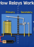
non-linearitiessuch as shock absorber damping, linkage friction and bump stops. Since the quarter car model is insucient to give information about the angular motions of a vehicle, some researchers used more complex models like half and full car models. These models give information about the pitch, roll and bounce motions of a vehicle body. Crolla and Abdel Hady(1991)comparedsomeactivesuspension control methods on a full car model. Integrated or ltered white noise was taken as the roadinput. The same researchers applied linear optimal control law to a similar model in 1992. Hrovat (1993) compared the performances of active and passive suspension systems on quarter, half and full car models using optimal control laws. Dry friction on dampers is one of the main factors aecting ride comfort. On good road surfaces and at low vehicle speeds, the eect of road input cannot overcome dry friction force and,therefore, the suspensions are almost locked, which is known as Boulevard Jerk, and an uncomfortable vibration mode becomes eective due to reduced degrees of freedom (Silvester, 1966). Some applications using non-linearity on active suspensions were achieved. Alleyne et al. (1993) compared sliding mode controlled active suspensions with PID controlled active suspensions. Yagiz et al. (2000) applied sliding mode controlled active suspensions to a linear 7 degrees of freedom vehicle model.A study has been carried out for linear motors where a satisfactory response to PID controllers can be obtained(Otten et al., 1997). The operatingprin-ciple of the linear motor is shown in Figure 1. It is
composed of 2 main parts. These are a number of base-mounted permanent magnets forming the stator and a translator formed by a number of iron-corecoils. By applying a 3-phase current to 3 adjoining coils of the translator, a sequence of attracting and repellingforces between the polesandthe permanentmagnets is generated. This results in a thrust force experienced by the translator. The motor is a synchronous, permanent-magnet motor with electronic commutation.
In this study, the aim is to compare some control strategies applied on the purely linear and harmoni-cally linearized non-linear full car model in order to obtain ride comfort using a PID control. A passen-ger seat is included in the vehicle model so that the response of the passenger due to a road disturbance can be observed. There are 3 strategies that have been taken into account. The rst strategy includes conventional suspensions and a controlled passenger seat. In the second strategy, the model has active suspensions and a normal passenger seat. The last model is fully controlled, i.e. both the suspensions and passenger seat have controllers.
Vehicle Model
The non-linear full car model used in this study is shown in Figure 2. It includes all possible control strategies. This full car model has 8 degrees of free-dom, namely x1,x2,x3,x4,x5,x6,x7= and x8= . These are the motion of the right front axle,the motion of the left front axle, the motion of the right rear axle, the motion of the left rear axle, the bounce motionofthe passenger seat, the bounce mo-tion of the vehicle body, the pitch motion of the ve-hicle body and the roll motion of the vehicle body,respectively. The aim is to improve the ride comfort of the passengers. The common application in mod-eling the vehicle with a passenger seat is to add only 1 passenger seat preferably in the driver seat posi-tion (Baumal et al., 1998) though considering only 1 suspended seat implies that other seats are assumed to be xed rigidly to the chassis. This assumption does not exactly match a physically real vehicle. In general, the state-space form of a non-linear dynamic system can be written as follows:
x_ = f (x)+[B]u (1)
Here, x =[x1x2x3::::x16]^T where x9 =_x1 ;x10 =x_2 and so on. f (x) is vector functions composed of rst order dierential equations that can be non-linear, [B] is the controller coecient matrix and u =[u1u2u3u4u5]^T is the control input vector writ-ten for the most general case in this study. f (x) and [B] are given in the Appendix along with the nomenclature of vehicle parameters. Mathemati-cally, u1;u2;u3 and u4 do not have to exist together. In order to control vehicle body motions, 3controller forces are sucient since the body has 3 degrees of freedom in this study. These are bounce, pitch and roll motions. But for practical reasons, 4 controllers parallel to the suspensions are introduced. The yaw motion is neglected. Finally, 5 controllers are used including the one under the passenger seat.
As mentioned before, the major non-linearity of the model comes from dry friction on the dampers.Geometric non-linearity has also been included. Dry frictiononthedampersdepends ontherelativespeed (Vr) between related damper ends. Experiments show that the dry friction model (Figure 3) has a viscous band character rather than being of a classi-cal bang-bang type. The band " is very small, and this prevents the complete locking of the suspension ends. Low speeds on perfect roads generate dry fric-tion force aroundR that practically (not ideally) locksthe suspension generatingahighequivalentvis-cous friction eect as introduced by Unlusoy and Ya-giz (1986). The band " only prevents ideal locking, as found by Yagiz(1986) after comparinghis simula-tion results with a set of experimental ones obtained by Unlusoy (1979). The parameters are given in the Appendix.
Simulation
In the simulation stage, rst the non-linear model is used in order to obtain time responses. Second, for the frequency responses, the non-linear dry friction model is harmonically linearized using a describing function method. Accelerometers are used as sen-sors. These sensors are placed only to measure the states to be controlled. The data provided by these sensors are processed by micro-controllershavingthe PID algorithms designed. The noise is ltered using a low-pass lter, which allows the signals within the frequency range of the related vehicle dynamics.
Frequency response of the vehicle model
Frequency response is another key to understand the behavior of a dynamic system. Frequency re-sponse analysis is the main tool in interpreting the dynamic behavior of vehicles. Since the frequency response plot of a non-linear system is dependent on input and is not unique (there are innite response plots for innite inputs), the dry friction model is harmonically linearized in frequency response anal-ysis whereas non-linear ones were used in time re-sponse analysis. Linearizationwithout ignoringnon-linearity is achieved by using the describing function method for dry friction on dampers as developed by Yagiz (1986) and assuming that the vehicle body an-gular motions are small. In this technique, the eect of a non-linear dry friction model is replaced by a linear equivalent damping coecient (Ce) obtained by the describing function method.
Conclusion
The mainideabehind proposingthiscontroller is the ability to use these types of controllers on vehicles with developing technology. PID control, which is easy to design and has good performance, has been applied. The simulation results prove that, among 3 control strategies considered, using controllers un-der the vehicle body and passenger seat will provide the best ride comfort. The rst case, only having a controller under the passenger seat, cannot guaran-teeridecomfortsinceitdoesnothavecontrolover the angular motions of the vehicle or the passenger. The second case, where only the vehicle body is un-der control, provides sucient vehicle motions, but it does not provide good control over passenger com-fort. Therefore, the third strategy should be taken into account by considering the control of the ve-hicle body and passenger seat together. Using the third strategy, the bounce motion of the passenger almost vanishes with an extra controller that applies very small force input. A successful improvement has also been obtained in the isolation of the verti-cal acceleration of passengers. Frequency response plots of a passenger for these alternatives support the results obtained. When frequency responses of the passenger seat for linear and non-linear models are compared for controlled and uncontrolled cases, the damper locking eect of dry friction is also ob- served. In conclusion, adding a controller under the passenger seat improves ride comfort greatly. |
|
 |手机版|小黑屋|Archiver|汽车工程师之家
( 渝ICP备18012993号-1 )
|手机版|小黑屋|Archiver|汽车工程师之家
( 渝ICP备18012993号-1 ) 深度剖析 2019-2020 概念车设计趋势
 智能座舱演进的思考


 IP卡
IP卡 狗仔卡
狗仔卡 发表于 18-3-2009 17:17:00
 提升卡
提升卡 置顶卡
置顶卡 沉默卡
沉默卡 喧嚣卡
喧嚣卡 变色卡
变色卡 显身卡
显身卡